It's working! Although construction isn't 100% finished as per the original design goals, it's close enough that it's now fully functional and accelerating protons.
Below is a video of a magnet sweep from 170 mT to 450 mT. The Dee RF frequency is fixed at 3.258 MHz. The second channel of the function generator is generating a triangle wave ramp waveform with a period of 600 seconds. This is effectively a slowly increasing DC voltage which is fed to the analog input control of the magnet power supply. As the field ramps from 170 mT to 450 mT, cyclotron resonances with the 3.257 MHz Dee voltage are hit. The main ones show below are 214 mT for H+ (ionized hydrogen atoms) and 427 mT for H2+ (ionized hydrogen molecules). There are other smaller ones present for harmonics of other trace gases (mostly nitrogen).
The scope is in XY mode, graphing the magnetic field (actually the ramp voltage controlling the field) with the X input, and the electrometer output on the Y. The electrometer has a 2V output signal that's proportional to the measured current. The scope is infinite persistence mode to display a complete graph of magnetic field vs. beam current. The raw field strength and beam currents are displayed on the two meters in real time while the trace is being generated. The beam spikes at the correct resonance points show that the cyclotron is working
Below is a scan from 0 to 178 mT. The peaks here are harmonics of the primary 214 mT resonance, which are at odd submultiples. For example, B/3 = 71 mT, B/5 = 43 mT, etc. These are present for H+ and H2+, as well as N+.
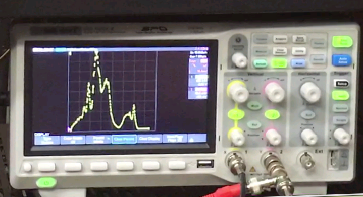 Scan from 0 to 178 mT
Here are the differences from the final design, and also some recent changes based on findings so far:
1. Dummy Dee not installed - this isn't strictly required in this design. The chamber lids are close enough to the main Dee that they can serve as a dummy Dee, since they're also grounded.
2. The 50W RF amp does not tolerate unmatched loads. After a few minutes, the two power transistors fail and must be replaced For now, the 5W pre-amp is sufficient for operation. We're getting 1300 Volts of RF on the Dee, which is enough to run the cyclotron. Going from 5W to 50W would only increase the voltage by a factor of sqrt(50/5), taking it to 4.1kV - worth doing, but not essential.
3. The Dee is not fixed in position in the chamber. This makes repeatable experiments more difficult.
4. Water cooling is not installed for magnet coils. This limits operation at high fields (over 450 mT) to about 90 minutes.